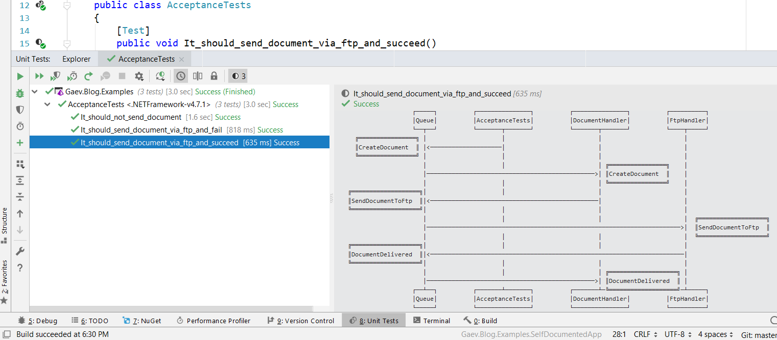
How does it work? What’s going on here? I usually have such impression while looking into an unfamiliar piece of source code. It can be even worse, for instance, in event-driven systems due to a low level of coupling, or in the microservice world when you are having a huge amount of standalone apps, or in serverless architecture with tones of independent functions.
Problem
In order to figure out, I take a piece of paper, pen and start to draw diagrams. After some time of Find Usages / Go to Implementation exercise and debugging session my diagrams are ready. Done! However, they are going to be outdated really soon. Can it be automated to have the diagrams without digging into source code every time?
Let’s imagine, we need to explore how the following system works. And we already have an acceptance test which sends a document to FTP.
[Test]
public void It_should_send_document_via_ftp_and_succeed()
{
    // Given
    IMessageBus bus = new InMemoryMessageBus();
    var documentHandler = new DocumentHandler(bus);
    var ftpHandler = new FtpHandler(bus);
    bus
        .Subscribe<CreateDocument>(documentHandler)
        .Subscribe<DocumentDelivered>(documentHandler)
        .Subscribe<DocumentFailed>(documentHandler)
        .Subscribe<SendDocumentToFtp>(ftpHandler);

    // When
    bus.Publish(new CreateDocument {Content = "Send to ftp://test.com please!"});

    // Then
    // Some assertion logic
}
The system uses the following infrastructure. Later, we will make use of it.
public interface IMessageBus
{
    void Publish(object message);
    IMessageBus Subscribe<T>(IHandle<T> handler);
}
public interface IHandle<T>
{
    void Handle(T message);
}
InMemoryMessageBus is in-memory message bus implementation of IMessageBus just to show you the idea. DocumentHandler, FtpHandler are message handlers that contain domain logic and speak between each other via messages.
Solution
I would like to share my idea on how to generate the diagrams automatically. Moreover, you don’t have to add any dependency to your application source code. Because all you need is logger, tests and a bit of PlantUML skills. I’m pretty sure you already have those first two. If not:
(╯°□°)╯︵ ┻━┻
The idea is using logger to write PlantUML code. The logger writes PlantUML code into a file system so multiple processes can use the same log file. The test runs a logic then reads PlantUML code from the log file and renders the diagram.
The following code does the magic just by wrapping IMessageBus.
public class PlantUmlDiagramBuilder : IMessageBus
{
    private readonly IMessageBus _bus;
    private readonly ILogger _logger;

    public PlantUmlDiagramBuilder(IMessageBus bus, ILogger logger)
    {
        _bus = bus;
        _logger = logger;
    }

    public void Publish(object message)
    {
        var callingType = new StackTrace().GetFrame(1).GetMethod().DeclaringType;
        _logger.Debug($"{callingType.Name} -> Queue\nnote left: {message.GetType().Name}");
        _bus.Publish(message);
    }

    public IMessageBus Subscribe<T>(IHandle<T> handler)
    {
        _bus.Subscribe(new HandlerWrapper<T>(handler, _logger));
        return this;
    }

    private class HandlerWrapper<T> : IHandle<T>
    {
        private readonly IHandle<T> _handler;
        private readonly ILogger _logger;

        public HandlerWrapper(IHandle<T> handler, ILogger logger)
        {
            _handler = handler;
            _logger = logger;
        }

        public void Handle(T message)
        {
            _logger.Debug($"Queue -> {_handler.GetType().Name}\nnote right: {message.GetType().Name}");
            _handler.Handle(message);
        }
    }
}
Pay attention to these 2 lines because they are writing PlantUML code. So log file will be filled by sequence diagram code.
...
_logger.Debug($"{callingType.Name} -> Queue\nnote left: {message.GetType().Name}");
...
_logger.Debug($"Queue -> {_handler.GetType().Name}\nnote right: {message.GetType().Name}");
...
As a result, the test turns into.
[Test]
public void It_should_send_document_via_ftp_and_succeed()
{
    // Given
    var plantUmlCode = new StringBuilder();
    IMessageBus bus = new InMemoryMessageBus();
    bus = new PlantUmlDiagramBuilder(bus, NewLogger(plantUmlCode));
    var documentHandler = new DocumentHandler(bus);
    var ftpHandler = new FtpHandler(bus);
    bus
        .Subscribe<CreateDocument>(documentHandler)
        .Subscribe<DocumentDelivered>(documentHandler)
        .Subscribe<DocumentFailed>(documentHandler)
        .Subscribe<SendDocumentToFtp>(ftpHandler);

    // When
    bus.Publish(new CreateDocument {Content = "Send to ftp://test.com please!"});

    // Then
    Console.Write(RenderAsciiDiagram(plantUmlCode));
}
The test generates the following sequence diagram PlantUML code.
AcceptanceTests -> Queue
note left: CreateDocument
Queue -> DocumentHandler
note right: CreateDocument
DocumentHandler -> Queue
note left: SendDocumentToFtp
Queue -> FtpHandler
note right: SendDocumentToFtp
FtpHandler -> Queue
note left: DocumentDelivered
Queue -> DocumentHandler
note right: DocumentDelivered
Look at that beautiful ASCII output in a test output window. Although, it is up to you to get SVG or PNG as well as ASCII. RenderAsciiDiagram uses PlantUml.Net to render remotely, so you don’t have to install PlantUML locally.

Building the self-documented system is something you can try right now with minimal effort. This way tests can give us even more value apart from their primary goal. I will be happy to hear what do you think. See complete example here Gaev.Blog.Examples.SelfDocumentedApp.